لوحة تحكم لمغذية الحيوانات الأوتوماتيكية OEM / ODM

لوحة تحكم لمغذية الحيوانات الأوتوماتيكية OEM / ODM

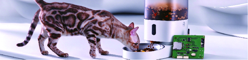
OEM / ODM Automatic Pet Feeder Control Board | ESP32-S3 with Wi-Fi, Bluetooth LE and a camera connector

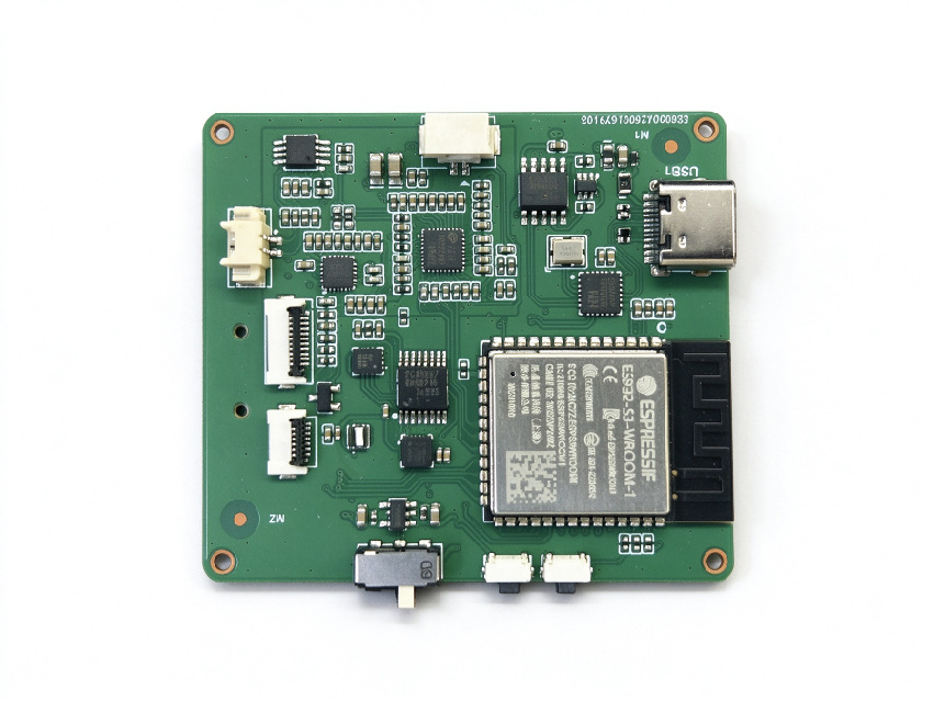
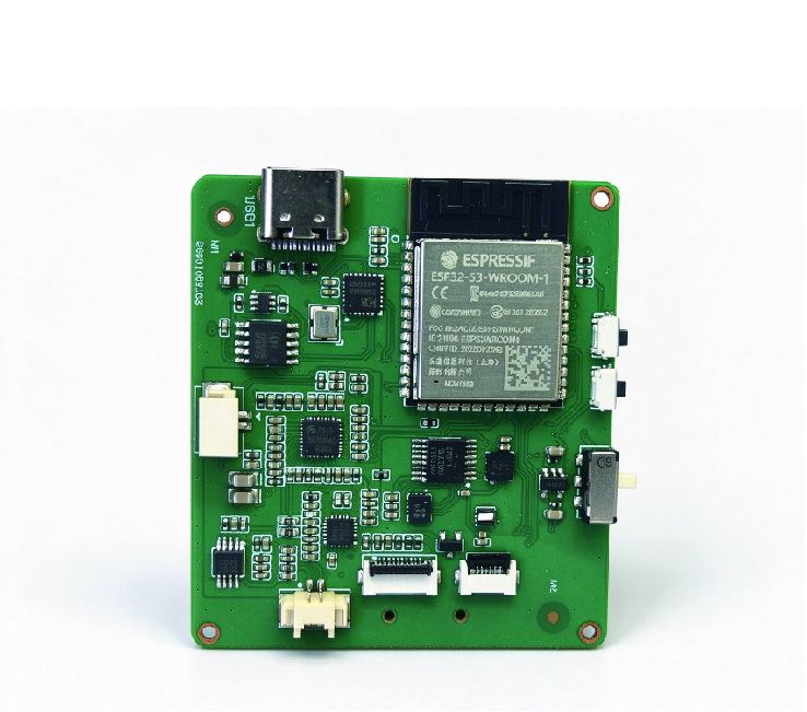
  • ESP32-S3-WROOM-1 module — Wi-Fi 2.4 GHz and Bluetooth LE 5 on one chip, no second radio board
  • Camera connector for a high-definition module, with the capture path handled in firmware
  • USB-C for power, firmware download and serial logs
  • Four keyed JST ports — motor, load cell, battery and sensor
  • MicroSD socket for local recordings and feeding history when the cloud is unreachable
  • Single tact switch for pairing and factory reset
Wi-Fi 2.4 GHz + BLE 5
One ESP32-S3 module, one antenna keep-out
Camera-ready
Connector and firmware path for a high-definition module
Four peripheral ports
Motor, load cell, battery and sensor, all keyed

Core PCBA Modules (Key BOM Components)

Every Smart Automatic Feeder PCBA produced by built from carefully selected, industry-proven components:

Key Components Industry Standards Core Inspection & Production Equipment
Main Control Chip (MCU / SoC-ESP32) IPC-7711 / 7721 High-speed Pick-and-Place Machine
Power Management (DC-DC, LDO, battery charge/discharge management) IPC J-STD-001 3D AOI (Automated Optical Inspection)
Motor Driver (Stepper / DC / Servo motor driver ICs) IPC-A-610 X-Ray Inspection System
Load Cell Interface (ADC chipsets such as HX711) WEEE In-line AOI + First Article Inspection (FAI)
Communication Module (Wi-Fi, Bluetooth, 4G, LoRa) Constant Temperature & Humidity Aging Chamber
Storage (EEPROM / Flash) EMC Pre-compliance Lab (Optional)
Human-Machine Interaction (buttons, LEDs, buzzers, LCDs) BGA / QFN / solder joint void inspection
Protection Circuits (ESD, overcurrent, reverse polarity protection) Laser Marking / Barcode Traceability System

سيناريوهات الأعمال B2B وقيمة البيع بالجملة

Development Considerations for Network-Enabled Pet Feeder Control Board

RF and Antenna Layout

1. Strict Keep-out Zone: Copper pours, traces and component placement are prohibited on all layers (including the bottom layer) within at least 15 mm directly beneath and around the antenna. If the antenna must be placed at the PCB edge, it is recommended to extend the antenna outside the board boundary.
2. Isolate from Interference Sources: The antenna shall be kept away from crystal oscillators, motor-drive inductors, high-current traces, batteries and metal structural parts. If harmonics from crystals or transient noise from motors couple into the antenna, the receiving sensitivity will degrade sharply.
3. Do Not Reuse Matching Network Parameters Directly: The π-type matching network (normally three components) on RF traces needs tuning based on the actual PCB substrate, stack-up and trace width. Parameters copied from other boards often cause impedance mismatch, resulting in low transmission efficiency and reduced communication range.

Power and Grounding Design

1、 Separate power supplies for motor and logic circuits: Motors (especially during startup) and Wi‑Fi transmission cause severe fluctuations on power rails. If the main MCU and HX711 share the same LDO with the motor, weight readings may jump when the motor runs, or even trigger MCU reset. Use independent LDOs or DC‑DC converters for analog and digital sections. Add sufficient decoupling capacitors at the input of the motor driver power supply.
2、 Analog ground layout for HX711: AGND and DGND of the HX711 shall be connected at a single point near the chip, instead of connecting arbitrarily to the main ground plane. Traces for the load cell should be kept as short as possible. Shielded cables are preferred with single‑ended grounding for the shield. Keep these traces away from motor driver lines and the Wi‑Fi antenna.
3、Transient response for Wi‑Fi power supply: The instantaneous current can reach hundreds of milliamps during Wi‑Fi transmission. If the 3.3V rail cannot respond fast enough, voltage sag will occur, leading to Wi‑Fi disconnection or MCU reboot. Place a large storage capacitor (100μF or higher) close to the module power pins and ensure the LDO has sufficient current margin.

Motor Driver Noise Suppression

1、 Motor-side filtering: A small ceramic capacitor (e.g., 0.1μF) connected in parallel across the motor terminals effectively absorbs high-frequency noise generated by commutation sparks. If space permits, add a TVS diode to clamp reverse voltage spikes.
2、 Isolate driver traces from sensitive areas: High-current motor driver traces should be kept short and wide. They must never run near the HX711 or the antenna keep-out zone. Twisted-pair wiring is recommended for external motor cables.

Software Optimization Strategies

1、 Adjustable Wi‑Fi transmit power: For indoor home applications where the distance to the router is relatively short, the maximum Wi‑Fi transmit power can be moderately reduced in firmware. This greatly reduces the impact of burst Wi‑Fi current on the power rail and lowers the risk of system anomalies caused by voltage sag.
2、Weight sampling scheduled away from motor operation: Never read HX711 while the motor is running. The correct timing sequence: wait tens to hundreds of milliseconds after the motor stops for the power supply and mechanical vibration to stabilize before sampling weight data. Median filtering or moving averaging is applied to smooth readings further.

A radio, a camera and a feeder driver on one board

A radio, a camera and a feeder driver on one board

The ESP32-S3 carries Wi-Fi and Bluetooth LE in the same package, so there is no second radio module to place, shield or certify.
The camera connector sits on the same board, and the capture path shares the module's own image interface — no USB camera bridge in between.

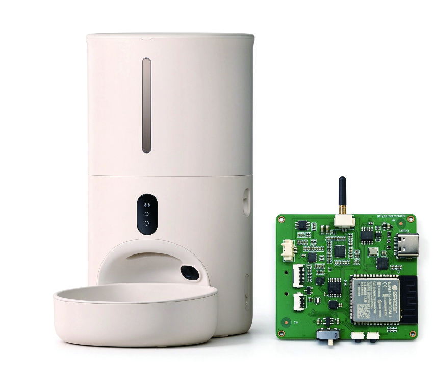
Small enough to fit the housing you already have

Small enough to fit the housing you already have

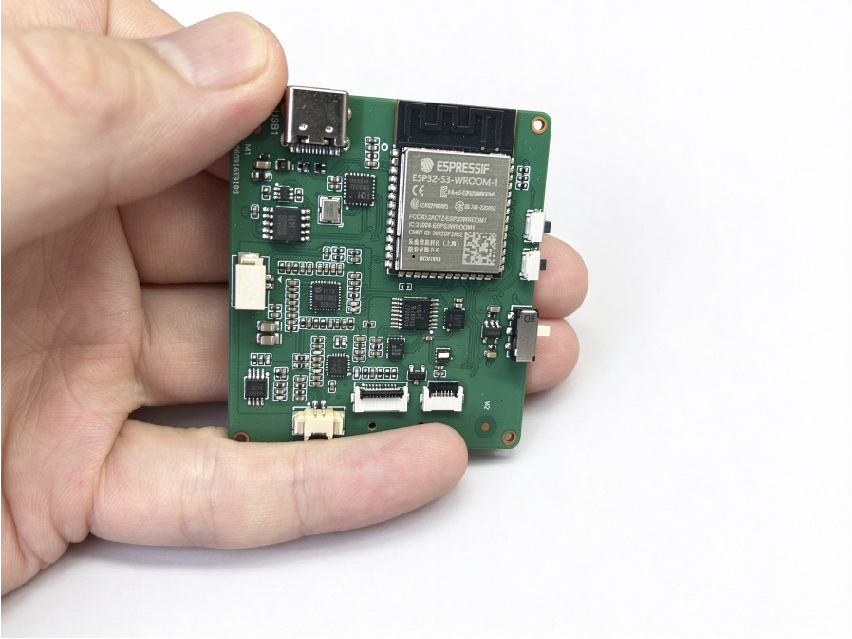
Roughly 1.89 x 2.13 in on two layers, with four M2 holes and every connector on the perimeter.
That is the size of a standard feeder control bay, so a board swap does not mean a new housing tool.

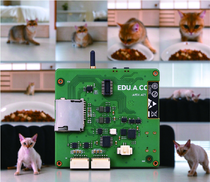
Support expandable local storage for feeding records and video clips.

Support expandable local storage for feeding records and video clips.

This pet feeder PCBA supports expandable local storage, which reliably stores feeding records and camera video footage. You can review historical feeding data and captured videos even when the network is unstable. It offers a stable offline backup solution and prevents loss of feeding logs and recordings caused by cloud disconnection.

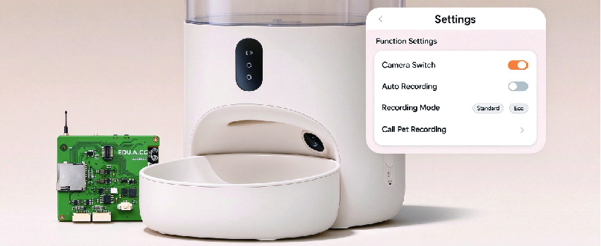
Smart Automatic Feeder PCBA camera

Smart Automatic Feeder PCBA camera

This smart pet feeder control board supports connection to an HD wide-angle camera. The lens features a 130° viewing angle with distortion kept under 8%, producing images that are nearly distortion‑free. When not in use, the system switches to ultra-low-power sleep mode. The onboard battery supplies power for the whole unit, maintaining standby monitoring without mains power.

Smart Automatic Feeder PCBA Manufacturer, Supplier & OEM/ODM Factory

One-Stop R&D, Design & Manufacturing Partner for Smart Pet Feeder PCBA

We are a manufacturer and factory of smart pet feeder PCBA circuits, serving global pet tech brands. Our offerings range from low-power battery-powered feeders to AI-powered pet recognition systems. Our one-stop OEM/ODM capabilities cover the full workflow: design, engineering development, prototyping and mass production.

Whether you need small-batch custom prototypes of smart feeder PCBA or large-volume wholesale for global distribution, we deliver end-to-end solutions. Our products comply with CE, FCC, RoHS, UL, KC, PSE and UKCA standards. We provide competitive pricing for automatic pet feeder PCBA together with industry-leading lead times.

Smart Automatic Feeder Product Overview

Smart automatic pet feeders are IoT devices built for the pet industry, integrating IoT connectivity, advanced sensors, precise motor control and cloud management functions. The core printed circuit board assembly (PCBA) inside every reliable feeder must feature four key characteristics:

Ultra-Low Power Consumption — Designed for battery-powered, round-the-clock standby operation
High Reliability — Supports unattended 24/7 operation in home environments, outdoor enclosures and breeding farms
Stable Wireless Connection — Reliable Wi-Fi, BLE (Bluetooth Low Energy) and 4G LTE Cat.1 communication
Precise Motor Drive Control — Accurate control for food dispensing, portion feeding and ration management

As an experienced supplier of smart pet feeder PCBA, we design every circuit board around these four core criteria to ensure trouble-free and stable performance of your finished products in real application scenarios.

Main Control Board PCBA

This is the brain of the smart feeder, integrating wireless connectivity, user interface, and timing logic.

Chipsets supported: ESP32, ESP32-S3, , Ingenic X1600, Allwinner XR872

Functions: Wi-Fi and BLE connectivity, touch button input, LCD/LED display driving, RTC timing, OTA firmware updates

Mounting precision: 01005 passive components, 0.4mm pitch BGA and QFN packages

Motor Driver Board PCBA

Power unit of the feeding system, used to control the rotation of the rotary conveyor, food dispensing of the stirring plate, and stall protection.

Driver IC: TB6612, DRV8871, L298N, A4988 stepper / DC motor driver
Functions: Drive auger conveyor motor and stirring plate motor, overcurrent protection, stall detection
Design features: Heavy copper traces of 2–4 oz for high current; dedicated thermal pads for MOSFET heat dissipation

Design Notes for Pet Feeder Control Board & Complete Unit Integration

This section covers integration rules of control board, battery compartment, touch keys, antenna and mechanical housing for reliable pet feeder development.

Capacitive touch buttons on pet feeder control board, anti-interference design to avoid accidental trigger, easy operation for users.

Capacitive touch buttons on pet feeder control board, anti-interference design to avoid accidental trigger, easy operation for users.

The touch keys on the feeder control board adopt capacitive touch design. The PCB layout shall keep touch sensing traces away from high-current motor lines, antenna tracks and power noise sources to avoid false triggering. Keep a reasonable thickness of the front panel cover plate, and reserve enough sensing area to guarantee stable touch response.

Where should the feeder control board be placed inside the battery compartment?

Where should the feeder control board be placed inside the battery compartment?

Position the control board adjacent to the battery compartment cable exit. Match the outlet position with the board connector for streamlined wiring. Keep cables clear of sharp edges of internal plastic parts to avoid wire abrasion, maintaining a clean harness layout. Seal the junction between battery compartment and control board with adhesive, which effectively prevents cable loosening caused by vibration.

Where should the control board be installed inside the pet feeder?

Where should the control board be installed inside the pet feeder?

Optimal layout for pet feeder control board: mount the PCBA at the feeder bottom with no metal shielding. We adopt a separate enclosed chamber for all electronic components to isolate electronics from food. This electric-food separation design prevents contamination from feed dust, preserves stable RF performance without metal shielding interference, and supports easy disassembly for maintenance.

Looking for Customization or Enterprise Bulk Orders?

We provide full-stack OEM/ODM manufacturing for pet feeder control boards — from firmware and app integration to enclosure-fit validation and global logistics.

Commercial Terms & Certification

الحد الأدنى للطلب OEM/ODM

The MOQ for customized firmware, silk-screen logo and gift box packaging is 500 pcs of boards. Single-board programming samples are available to verify camera, voice call and RF functions before mass production.

مهلة الإنتاج

PCB fabrication (standard 2 layers) 5-7 working days; 48-72 hours for rush orders

Assembly, programming and test 3-5 working days for 500 boards

التغليف القياسي

1pcs x Assembled and Programmed Control Board

1pcs x Anti-Static Bag

1pcs x Tray Insert

1pcs x Quick-Start Card (optional, your artwork)

Prices are quoted against a confirmed BOM and quantity. Tooling, programming fixtures and the first-article check are charged once on the first order.

Certification Support

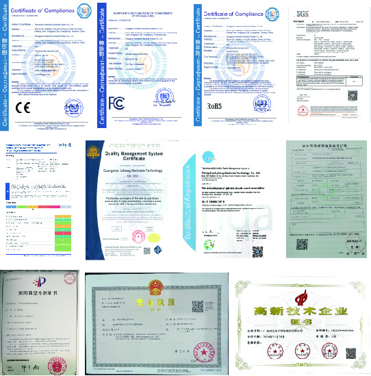
We will prepare the submission documents for the below certifications and conduct pre-compliance testing before sample delivery. The certificates will be issued to your side (brand owner), while test reports will be retained and filed by us.

RoHS REACH SVHC CE FCC UL CCC

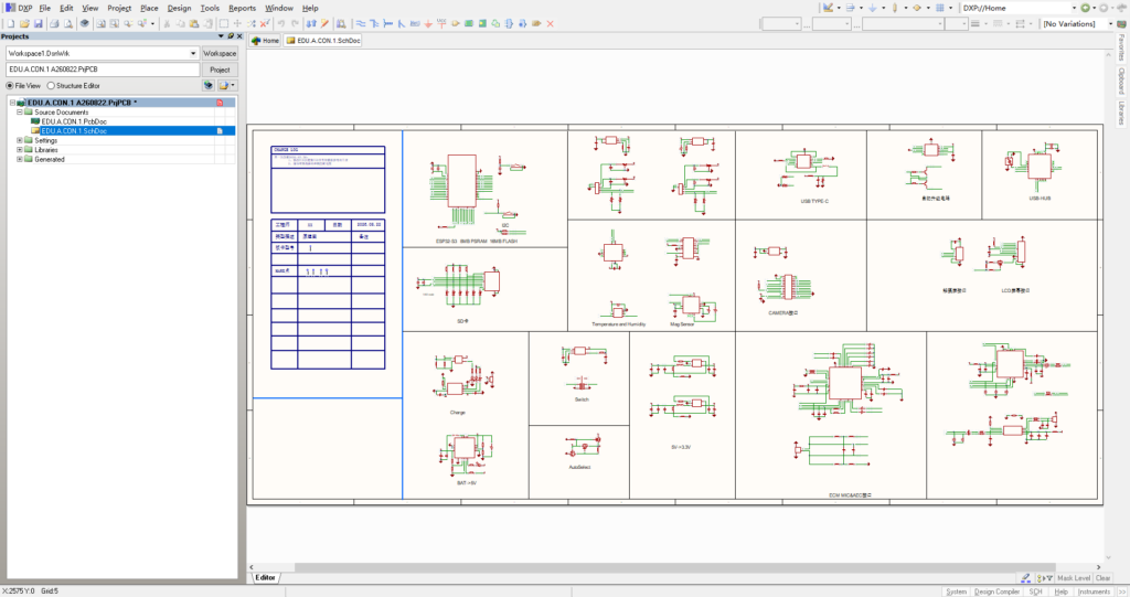
Schematic Design and PCB Layout of Pet Feeder Control Board

We provide hardware design, multi‑layer PCB selection, functional verification and analysis, embedded firmware development, with rapid first sample submission.

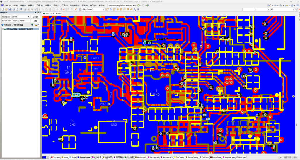
Schematic — ESP32-S3, camera connector, motor driver, load cell front end Schematic — ESP32-S3, camera connector, motor driver, load cell front end
PCB layout — 1.89 x 2.13 in, four layers, connectors on the perimeter PCB layout — 1.89 x 2.13 in, four layers, connectors on the perimeter

Built Around the Camera, Not Added On Later

Most feeder boards reach the camera by bolting a USB camera module onto a board designed for weight and motors. That works until you ask for a live view, because the capture path, the radio and the load cell are fighting for the same bus.

board starts from the ESP32-S3, so the camera sits on the module's own image interface and the Wi-Fi stream is fed from the same memory the feeder logic runs in. The load cell, the motor and the camera are scheduled together in firmware rather than bolted together in hardware.

The rest of the board is deliberately ordinary: a USB-C port for power and logs, a microSD socket for local history, four keyed JST ports for the mechanics of a feeder, and one tact switch for pairing. Ordinary parts are what keep a 500-board batch reproducible.

If your enclosure is already tooled, send the drawing. If it is not, send the mechanics and we will place the connectors around the camera instead of the camera around the connectors.

This

Successful Case Introduction: Pet Feeder Control Board

Case A — EU-Standard 6L WiFi Smart Feeder
PCB: 4-layer, 1.6mm, TG150, ENIG finish, 80×60mm dimensions

Main controller: ESP32-S3-WROOM-1, N16R8 (16MB Flash + 8MB PSRAM)

Motor: 12V DC gear motor with TB6612 dual-channel driver

Power supply: 5V/3A AC-DC adapter, with 4×AA battery backup

Certifications: CE-RED, FCC, RoHS

Case B — North American AI Camera Feeder
PCB: 6-layer HDI, 1.0mm, ENIG finish, Any-layer micro-vias

AI solution: Rockchip RV1103 paired with 1080P MIPI camera

Features: AI pet recognition, two-way audio, weight-based dispensing with ±1g accuracy

Certifications: FCC ID, UL-certified power supply

Technical Specifications

Controller module

ESP32-S3-WROOM-1, dual-core Xtensa LX7

Wireless

Wi-Fi 2.4 GHz 802.11 b/g/n, Bluetooth LE 5

Camera interface

High-definition camera connector (DVP or SPI module)

On-board storage

MicroSD socket, push-push

Host interface

USB-C — power, firmware download, serial log

Peripheral ports

4 x keyed JST: motor, load cell, battery, sensor

User control

Tact switch for pairing and factory reset

Board size

1.89 x 2.13 in

Stack-up

2 layers, 0.063 in FR-4, immersion gold

Mounting

4 x M2 plated holes

Power input

5 V via USB-C / 3.7 V Li-ion via the battery port

الحد الأدنى للطلب

500 boards (custom firmware, logo and packaging)

From Enclosure Drawing to Programmed Batch

الخطوة 1 Requirement confirmation and initial review: enclosure drawings, camera module parameters, voice specifications, application protocols and target order quantity. Send Requirements
الخطوة 2 Sample Assembly & Verification — Single programmable board, radio module, camera, network pairing and other items are tested in accordance with your requirements.
الخطوة 3 Pilot Batch and Certification Evidence — 50 to 100 boards, pre-compliance checks, test fixtures signed off.
الخطوة 4 Mass Production and Shipment — 500 boards and up, QR-traced, programmed, tested and packed to your artwork.

الوثائق والموارد الفنية

Can we see the schematic and the layout before we commit to a batch?

Yes. At the sample stage we send the Gerber files, the BOM and the assembly drawing so your engineers can review them. The source files — schematic, layout and firmware — are released on the first order, or earlier against an NDA.

What test evidence comes with a batch?

Each batch ships with an AOI report, an in-circuit and functional test summary, and the aging log from the burn-in rack. Every board carries a QR mark that resolves to its own test record, so a single unit can be traced back to the panel and the firmware version it was flashed with.

Which documents do we need if we apply for certification ourselves?

We hand over the schematic, the BOM, the PCB stack-up, the pre-compliance test report and the label artwork. That is the full package a test house asks for; if you would rather we handle the submission, we do that too.

Do you keep the firmware for batches you built earlier?

We keep the released image for every build, keyed to the batch, so a unit from last year can be re-flashed with the version it shipped with rather than the current one. If you need a rollback, tell us the batch and we will pull that image.

ما الملفات المطلوبة لعرض السعر؟

Please send Gerber files, BOM, XY/centroid data, schematics, required quantity and testing requirements. For new development, please share the product specification and function list.

FREQUENTLY ASKED QUESTIONS - CONTROL BOARDS

Does the board support Wi-Fi, Bluetooth and a camera at the same time?

Yes. The ESP32-S3-WROOM-1 carries Wi-Fi 2.4 GHz and Bluetooth LE 5 in one module, and the camera runs on the module's own image interface. Wi-Fi, BLE and capture share the radio and memory budget, so we fix the frame rate and the streaming profile during the sample stage rather than promising both at full rate.

Which camera modules can be connected?

A DVP or SPI camera module up to the resolution the S3 can capture and stream. Tell us the module you have in mind, or send us one, and we will confirm the connector, the pin order and the achievable frame rate on the sample.

Will it drop into the housing we already have?

The board is roughly 1.89 x 2.13 in with four M2 holes and every connector on the perimeter, which is the size of a standard feeder control bay. Send the enclosure drawing or a sample and we will confirm the fit before tooling.

Who writes the firmware, and can we use our own?

Either. We write the feeder logic, the camera pipeline and the app protocol as part of the project, or we ship a blank board with our board support package and your team takes it from there. The source stays yours.

What is the minimum order?

Custom firmware, logo marking and gift-box packaging start at 500 boards. Programmed samples are supported from a single board so the radio and camera can be validated first.

How is a batch traced if something goes wrong in the field?

Each board carries its own QR mark, and that mark resolves to the panel it was built on, the firmware version flashed into it and the test log from its final check. A field return tells us which batch to look at.

لماذا تختارنا

Top Tier OEM/ODM 20+ Years | Custom Large Smart Pet Products

أكثر من مليون
Annual Capacity
30+
R&D Team
ODM/OEM
20+ Years
الشهادات
CE/FCC/RoHS/FDA/IEC62368

الشهادات الدولية

نحن شركة عالية التقنية تجمع البحث والتطوير والإنتاج والمبيعات، ولدينا فريق متخصص في التصميم الصناعي والإلكتروني والإنشائي. حاصلون على ISO9001 وBSCI ونخدم أكثر من 200 عميل حول العالم.

الشهادات الدولية
FCC
CE
CE-EMC
REACH
RoHS
UN38.3
IEC62368
FDA
FCM
GPSD
UL/ETL IEC62368-1
FCM EU 10/2011
UL94

اتصل بنا نحن

يسعدنا التواصل معك!

العودة إلى جميع الخدمات