
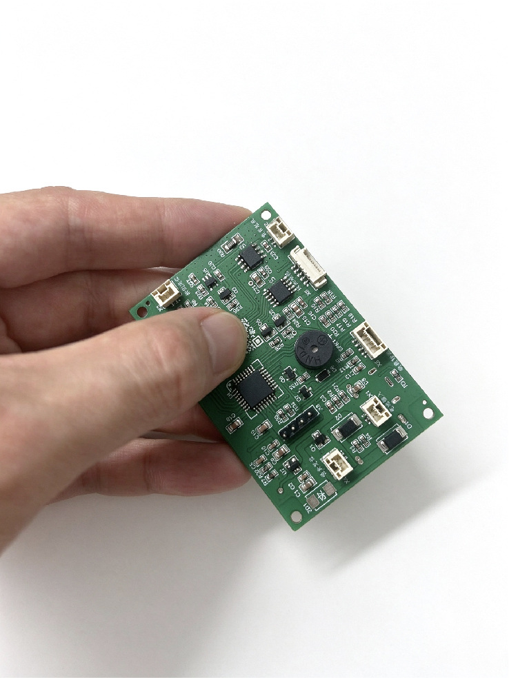
Our custom control board is developed for automatic pet feeders. It can adapt to various feeder machines including cat feeders, parrot feeders, large kibble feeders, grain feeders, dry food and wet food feeders.
By flashing different firmware, one control board can realize different sets of functions to match your product definition.
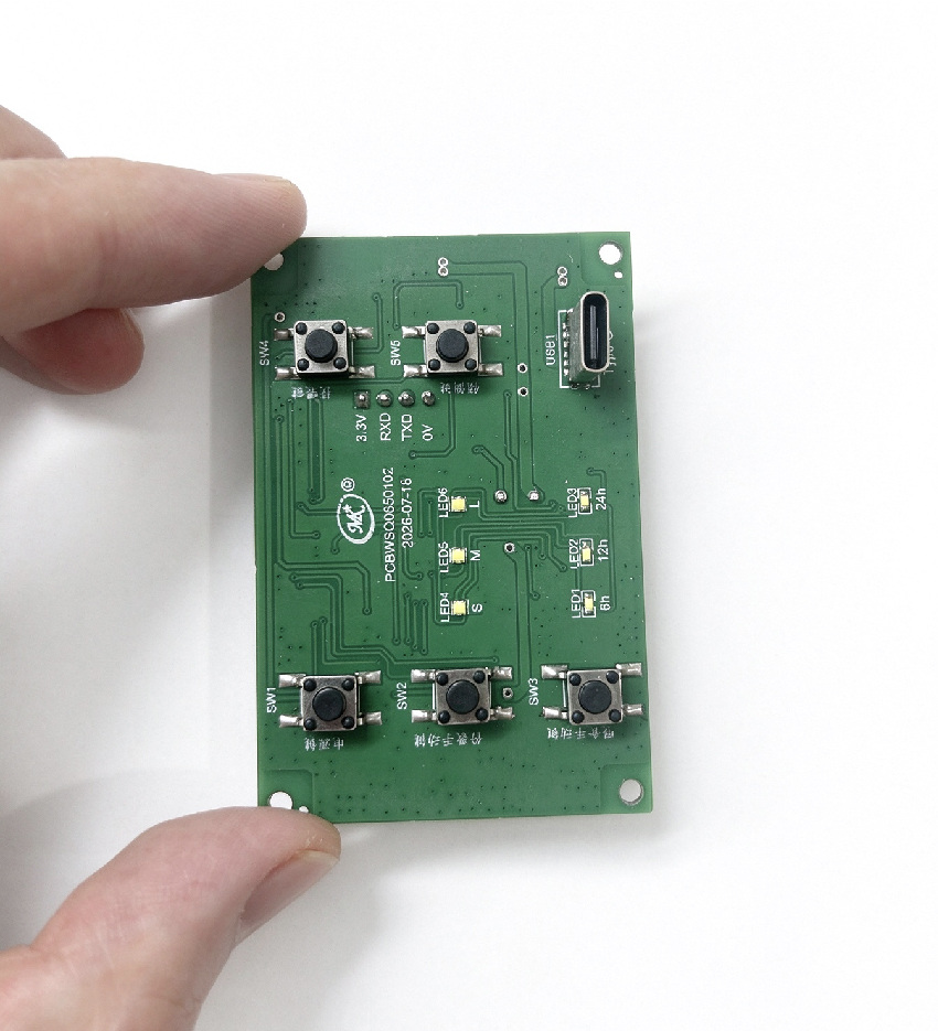
This PCBA supports manual feeding, automatic feeding, feeding schedule setting and remote feeding. It comes with low feed reminder and jam reminder, paired with proximity sensor.
Adopting ultra-low power design, it supports both external power supply and built-in battery power supply for long standby. OTA remote upgrade and local control are optional.
We can customize technical indicators, external interfaces and sensors to fit your project requirements perfectly.
Индивидуальная разработка платы управления кормушкой
Custom PCBA for smart pet feeder & water fountain
- - Custom WiFi control board for automatic pet feeder
- - Smart cat feeder main control board
- - Pet feeder motor control board with low food sensor
- - OTA enabled pet feeder control board
- - Pet feeder PCBA control board
Control board design and PCBA manufacturer - ODM and OEM
custom pet feeder control board, one board carrying the feed logic, the motor drive and the sensors Firmware, the app protocol and the connector set are built around your feeder, and every board is programmed and function-tested before it is packed.
Custom Pet Feeder Control Board Parameter List | ODM PCB & PCBA
Custom parameters of the pet feeder control board, support ODM, OTA upgrade, local control, ultra-low power design for automatic pet feeders.
| Technical Specifications | Applicable Models | External Interfaces |
|---|---|---|
| Low Feed Alert | Automatic Cat Feeder | Type-C |
| Jam Alert | Автокормушка для попугаев | Ultra-low Power Consumption |
| Proximity Sensor | Multi-feed Feeder | External Power Interface |
| Manual Feeding | Large Kibble Feeder | Built-in Battery Power Interface |
| Automatic Feeding | Grain Feeder | Long Standby Time |
| Feeding Schedule Setting | Wet Food Automatic Feeder | Support OTA remote upgrade |
| Remote Feeding | Dry Food Automatic Feeder |
B2B-сценарии и оптовая ценность
Compatible with multiple automatic feeders. Different firmware can be flashed to realize various functional requirements.
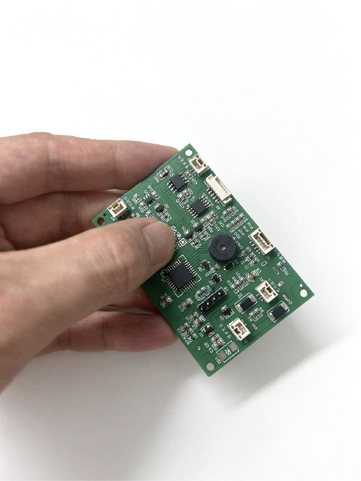
Custom Pet Feeder Control Board | Lockable Cable Connector, Anti-loose & Anti-disconnect
Our custom automatic pet feeder control board is equipped with a lockable cable connector design. The locking structure secures the cable tightly, preventing loose connections during transit. It also avoids poor electrical contact when pets knock or tip over the feeder in daily use, delivering stable and reliable power supply all the time.
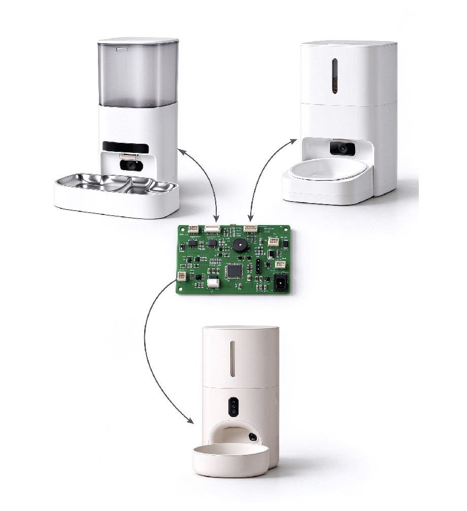
Automatic feeder control board compatible with a wide range of feeder models.
1、We adopt a universal-size PCBA design for the pet feeder control board. The circuit board keeps the same outer dimensions while supporting different feeder products. It is structurally compatible with multiple feeder housings, eliminating the need to develop separate PCB outlines for each model. This greatly reduces custom board development costs and shortens your project lead time.
2、custom pet feeder control board, lockable cable connector pet feeder pcba, anti loose power interface feeder controller, pet feeder board anti disconnect when tipped over, automatic cat feeder control board, automatic parrot feeder pcba, wet food feeder control board, ultra low power pet feeder board
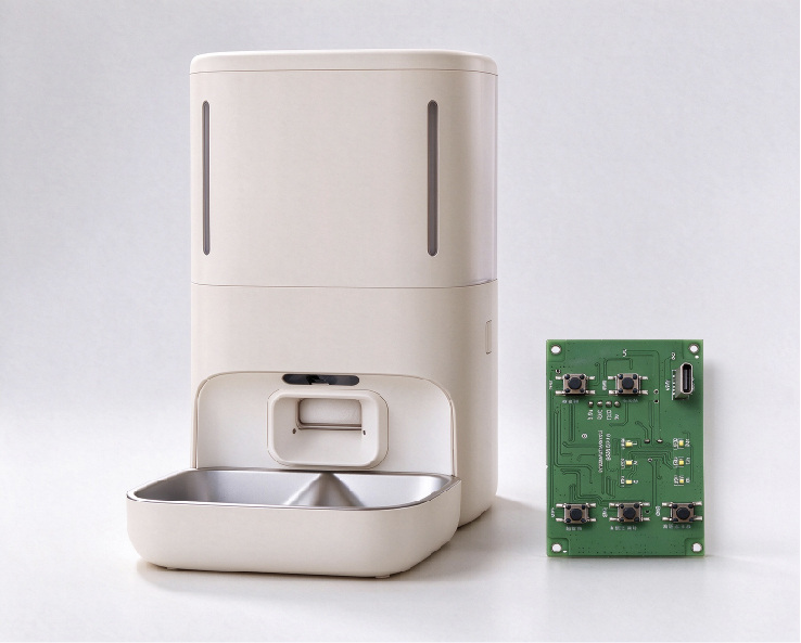
Custom ODM PCBA for smart automatic pet feeders
1、The standard PCB stack-up for pet feeder control boards is 4-layer. If you require a smaller overall size, we can adopt a 6-layer PCB design with miniaturized components to realize space-saving layout.
2、This feeder control board features multi-power supply design. It can work with built-in rechargeable lithium battery, AA batteries, or Type‑C power input. The flexible power scheme guarantees normal feeding operation and solves the power cut backup issue.
Considerations for Ultra-Low-Power MCU Selection
Key considerations when selecting ultra-low-power MCUs for battery-powered pet feeder PCBA projects, including sleep current, wake-up time, peripheral power domains, supply voltage range and RTC performance.
Customers mainly focus on the following issues:
1. Sleep & standby current
2. Wake-up latency
3. RTC clock accuracy
4. Peripheral power gating
5. Operating voltage range
6. ADC sampling precision & power consumption
7. Firmware power management strategy
8. EMC/ESD performance
9. OTA upgrade reliability under low voltage
10. Chip supply continuity & lead time
Below are the mandatory test items that must be performed.
1. Product Aging Test
2. High & Low Temperature Test
3. Salt Spray Test
4. Connector Insertion & Extraction Test
5. High Temperature & High Humidity Test
6. Button Life Test
7. Drop Test
PCBA Manufacturing Challenges We Master
1. Irregular PCB and Panelization Process — Smart feeder housings feature a compact structure, which usually requires irregular-shaped main PCBs. Our panelization technology is a core part of our automatic feeder PCB design service.
2. BGA and QFN Soldering — WiFi modules, AI chips and new-generation STM32 PCBA solutions for smart pet feeders widely use BGA or QFN packages. Our optimized reflow soldering process enables high-yield and highly reliable assembly for these packages.
3. Mini-LED and Micro Connector Soldering — Product miniaturization drives the extensive adoption of tiny FPC connectors, Micro-USB and Type-C ports. Our SMT production line achieves a placement accuracy of ±0.03 mm.
4. Conformal Coating — Selective coating or full-board conformal coating is available for moisture, dust and corrosion protection, provided as a standard service.
5. Sensor Calibration — Load cells, temperature sensors and liquid level sensors complete firmware flashing, calibration and performance verification before shipment.
6. OTA Pre-flashing & Flexible Production — Mass firmware pre-flashing and OTA workflow management are integrated into our production process. We support multi-SKU small-batch production. Our flexible manufacturing model is tailored for customers managing numerous SKUs with short iteration cycles.
7. Collaborative DFM Optimization — If customer designs lack standard specifications, our engineering team offers free design optimization recommendations.
Summary on Safety and Reliability Design of Pet Feeder Control Board
The hardware schematic design and PCB layout determine whether the control board can work stably for a long time. They are the core points to reduce defect rates in large-scale production.
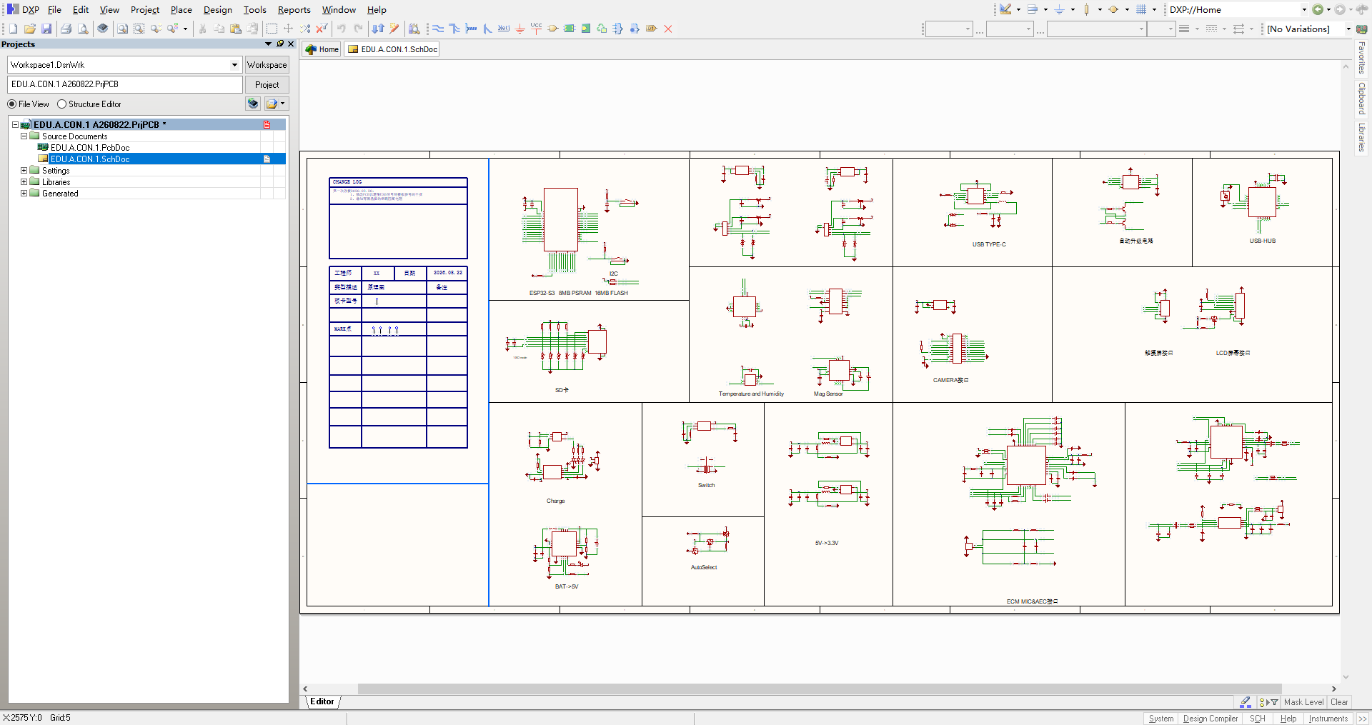
Key Points for Schematic Design of Pet Feeder Control Board
1. Driver IC Selection and Protection: The schematic incorporates freewheeling diodes or utilizes the built-in protection of the driver IC to absorb back EMF generated during motor start and stop, protecting the main MCU and driver IC from breakdown. 2. Food Jam Prevention Design: The schematic supports motor current sampling for real-time current monitoring by the MCU. When food jams, the motor stall current rises abnormally, and the MCU activates the reverse rotation logic to clear the blockage. 3. Load Cell Interface: Adequate filtering and decoupling are required between analog and digital circuits. Load cell signal traces should be kept short and routed away from switching power supplies and motor driver traces. Otherwise, noise from the running motor will interfere with weight readings and cause inaccurate food dispensing. 4. Multiple Voltage Domains and Isolation: The main controller generally runs on 3.3V, while motors and some peripherals require 5V or 12V. If LDOs are used to step down from a higher voltage, power consumption and heat dissipation must be calculated. Isolation should be implemented between the motor power supply and MCU power supply. Without isolation, voltage dips at motor startup may cause MCU reset or Wi‑Fi module disconnection.
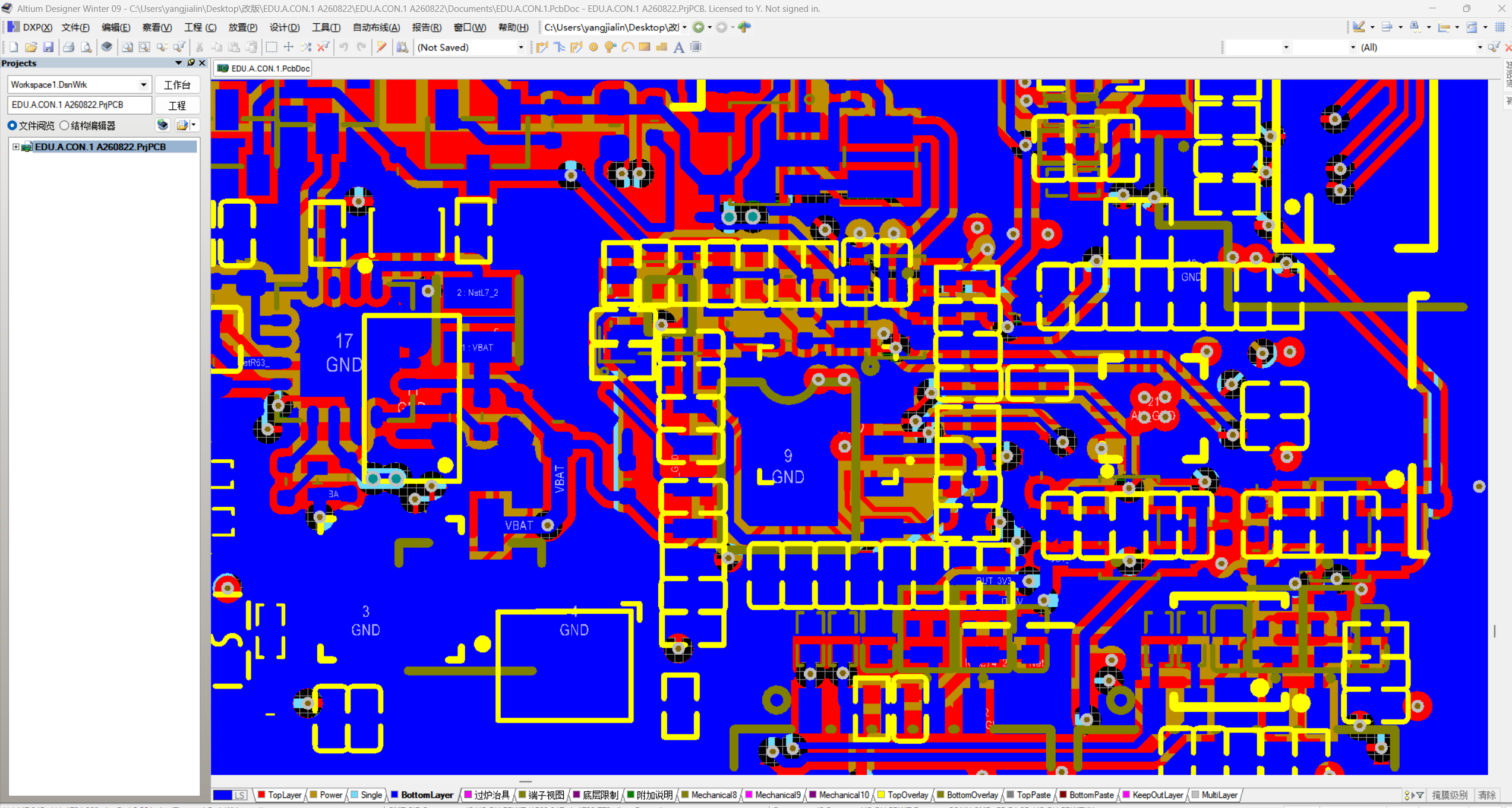
Important Layout Guidelines for Pet Feeder Control Board PCB
1. Route power loops first: Prioritize routing the loop among the motor driver IC, motor connector, freewheeling diode/capacitor and input power filter capacitor before laying out other signal traces. Keep this loop area as small as possible, since high-amplitude trapezoidal current tends to radiate interference. 2. Physical partition: Isolate the motor power area from the 3.3V power domain for the MCU and load cell chip. High-current motor traces shall not run underneath the MCU or HX711. Separate them with ground traces or physical clearance gaps. 3. Keep away from motors and DC-DC: The load cell chip and its surrounding filter capacitors must be placed far from the motor driver IC, motor connector, inductors and all switching power traces. 4. Crystal close to MCU: Place the crystal oscillator as near as possible to the MCU clock pin (recommended distance < 8 mm). No high-speed signal or power traces are allowed underneath it. Surround the crystal with ground copper and add shielding vias.
Looking for Customization or Enterprise Bulk Orders?
We provide full-stack OEM/ODM manufacturing, solution development, hardware & software design, and mass production services for this hardware.
Rapid Custom Design
Rapid Custom PCB Design for Pet Feeder Control Boards
Embedded Software Development
Compile the interaction logic of the local control module according to requirements, optimize and streamline the code to reduce memory footprint.
Motor Control Logic
Support motor stall detection and forward/reverse rotation logic via motor drive firmware compilation.
Sensors Control
Control sensor logic for low-food detection, jam detection, weight measurement and feeder proximity sensing
ИНТЕГРАЦИЯ КОММЕРЧЕСКИХ ПОСТАВОК
- MOQ OEM/ODM
Custom firmware, logo marking and gift-box packaging start at 500 boards. Programmed samples are supported from 1 board.
- Срок производства
PCB Manufacturing (Standard 4–6 layers)
5–7 working days; 48–72 hours for rush orders
PCB Manufacturing (8+ layers / HDI) 8–12 working days
PCBA Prototyping 5–7 working days (after PCB & components are ready)
PCBA Mass Production 7–15 working days (depending on volume & BOM readiness)
Full Turnkey (including component sourcing) 15–25 working days
- Стандартная упаковка
Standard Package List:
1pcs x Assembled and Programmed Board
1pcs x Anti-Static Bag
1pcs x Tray Insert
1pcs x Batch Test Report
1pcs x Packing Carton
СООТВЕТСТВИЕ И СТРОГИЕ СТАНДАРТЫ
Boards are assembled under factory supervision, programmed on the line and function-tested before they are bagged. Material declarations for the populated components travel with every shipment, alongside the batch test report, and the assembly is supplied to partners across Europe, North America and worldwide markets.
Our Advantages for Smart Pet Feeder Control Boards
✅ One-stop solution: PCB design, fabrication, component procurement, SMT, assembly, testing, aging & global delivery
✅ Mature solution matrix: 20+ mass-produced smart feeder models for EU, US, SEA & MENA; portion-control, low-power and rechargeable feeder PCBA available
✅ IoT ecosystem integration: Tuya, HomeKit, Google Home, AWS IoT, Alibaba Cloud IoT compatible
✅ Certification service: FCC, CE, RoHS, UL, PSE, CCC, KC application support
✅ Flexible capacity: 50pcs prototype to 10,000pcs mass production; 7-day rush order available
✅ Global shipping: FOB / CIF / DDP, direct shipment to Amazon FBA and overseas warehouses
✅ Strict quality control: AOI, ICT, FCT and aging test to guarantee reliable PCBA output
Deep Expertise in Smart Feeder Electronics
✅Years of focused experience in pet-tech manufacturing have made us a trusted partner for Automatic Pet Feeder PCBA and Smart Pet Feeder PCBA projects worldwide. We bring proven capability in:
✅Mounting and firmware programming for Wi-Fi, BLE, and Zigbee modules, including ESP32, ESP8266, RTL8710, and NRF52832.
✅Designing and assembling typical feeder circuits such as load cells (HX711, NAU7802), IR sensors, Hall sensors, and brushed/brushless motor drivers.
✅Power integrity optimization and EMC pre-compliance design, ensuring high first-pass certification rates for CE, FCC, UL, and RCM approvals.
✅Whether you are developing a programmable feeder PCBA with portion control, an intelligent pet feeder PCBA with AI-driven feeding logic, or a multi-pet smart feeder mainboard, our engineering depth accelerates your time-to-market.
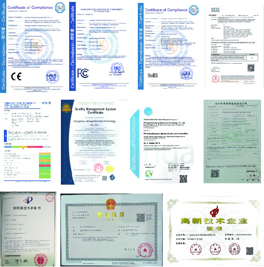
Qualifications & Certifications
System Certifications
ISO 9001:2015 Quality Management System Certification
ISO 14001:2015 Environmental Management System Certification
ISO 45001:2018 Occupational Health & Safety Certification (value-add)
Industry Certifications
UL Certification
CQC / CCC
IATF 16949
Environmental Compliance
RoHS 2.0 Declaration of Conformity
REACH SVHC Report
Halogen-Free Test Report
Conflict Minerals Reporting Template (CMRT) Declaration — required by major European and US clients
Технические характеристики
Board Type
Single-board controller for a timed-dispense pet feeder
Microcontroller
48-pin LQFP, programmed and function-tested before packing
Motor Drive
Two on-board driver stages, one for the gate and one for the auger
Connectors
Keyed JST headers for the motor, sensors, buttons, LED and power lead
Audible Alert
On-board piezo buzzer for a blocked chute or an empty hopper
Programming Header
On-board header, so a board can be flashed and re-tested after assembly
Traceability
QR mark on every board, batch traceable to its panel and component reels
Mounting
Four corner holes, spaced to your housing
Surface Finish
Green solder mask with white silkscreen
Board Outline
Cut to your drawing, including cut-outs and edge connectors
Firmware
Written for your feeder, with the feeder logic and the app protocol in one image
Testing
Function-tested on the line; the batch report travels with the carton
Tooling
No board tooling to amortise - the layout belongs to you
Упаковка
Anti-static bag, tray and carton, with the batch test report
Варианты кастомизации
Schematic, layout, connector set, firmware and enclosure fit built to your drawing
Подходит для
Smart pet feeders and comparable timed-dispense appliances
From Control Board Requirement Specification to Mass Production
FREQUENTLY ASKED QUESTIONS - CONTROL BOARDS
Can you build a board that drops into a housing we already have?
Yes. Send the housing drawing, a 3D file or a sample, and the board outline, the connector positions and the mounting holes are laid out to fit it. The first boards come with a fit check before the batch runs, so a connector that fouls a rib or a boss is caught while the layout is still cheap to change.
Who writes the firmware, and can we use our own?
Either way. We write the feeder logic and the app protocol as part of the project, so the board and the app ship in step. If you already have a binary, we program yours instead and report the firmware version per batch, so a board can never leave with the wrong image on it.
How is a batch traced if something goes wrong in the field?
Each board carries its own QR mark. That mark resolves to the panel it was cut from, the component reels that went into it and the test record from the line, so a unit that comes back can be traced back to the run and the reels rather than to a shipment in general.
What is the minimum order, and what does the first order include?
Custom firmware, logo marking and gift-box packaging start at 500 boards. A first batch ships assembled, programmed and tested, each board in an anti-static bag on a tray insert. Programmed samples are supported from a single board, so the firmware can be proven before the batch is released.
Can you work from our schematic, or do you design the board?
Either. Send a schematic and we take it through layout, sourcing, assembly and test. Send only a functional specification and we take it through schematic, layout, firmware and test. The design files remain yours either way.
Which certifications can you support, and who holds the certificate?
We prepare the submission evidence for CE, FCC, RoHS, REACH SVHC, UL, PSE, CCC and KC, and we run pre-compliance checks before the sample goes out so the first submission is not wasted. The certificate is issued to you as the brand owner; we keep the test reports on file.
What happens if the firmware needs a change after the boards are made?
The boards are programmed through a pogo-pin fixture or a connector header, so a firmware change is a re-flash rather than a new board revision. On designs with an OTA path, we hand over the update package and the signing keys stay with you.
How is the price staged, and what does a repeat order cost?
The board price is quoted against a confirmed quantity and BOM. Tooling, programming fixtures and the first article check are charged once, on the first order. A repeat order on the same BOM does not carry those charges again; a BOM change is quoted separately before anything is built.
How do you protect our design and our firmware?
An NDA is signed before drawings change hands. Programming happens in-house on an encrypted image, and the read-out protection bit is set on every board unless you ask for it to be left open. Physical access to the SMT and programming areas is logged.
Какие файлы нужны для расчёта стоимости?
Please send Gerber files, BOM, XY/centroid data, schematics, required quantity and testing requirements. For new development, please share the product specification and function list.
ПОЧЕМУ МЫ
Top Tier OEM/ODM 20+ Years | Custom Large Smart Pet Products
Международные сертификаты
Мы высокотехнологичная компания, объединяющая НИОКР, производство и продажи. Сертификаты ISO9001 и BSCI, обслуживаем более 200 клиентов по всему миру.
Контакты нас
Будем рады вам помочь!